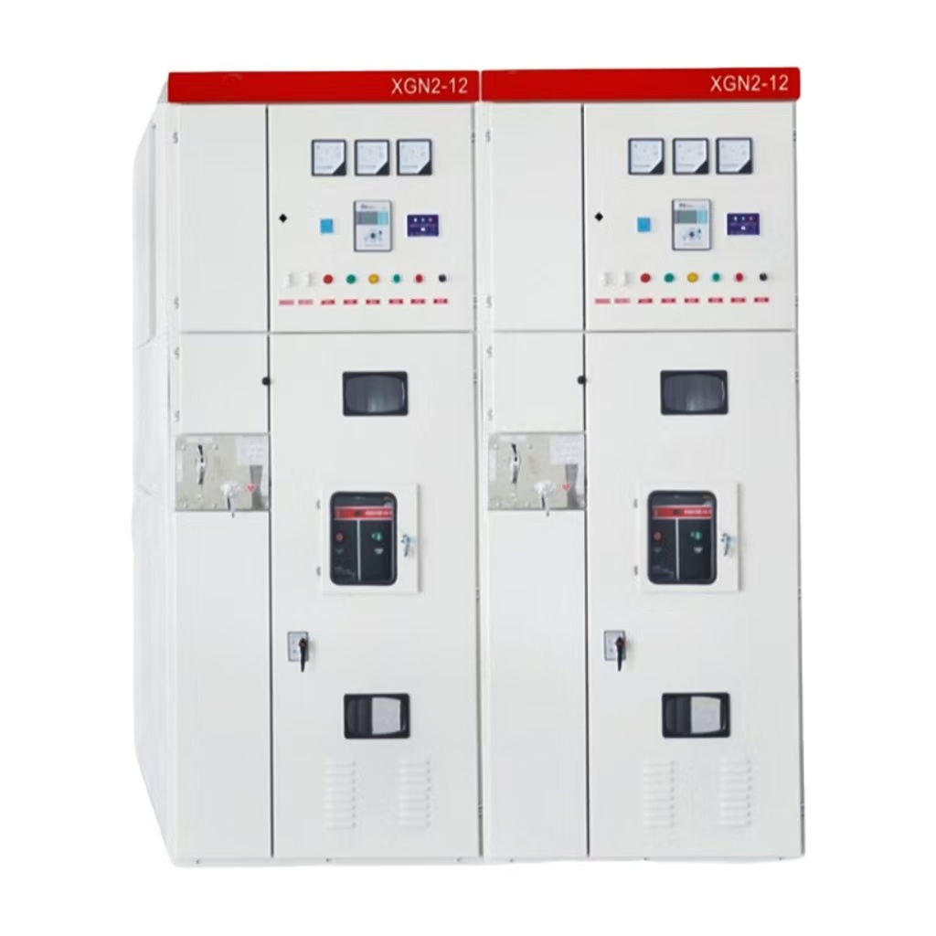
XGN2-12 box-type fixed metal-enclosed switchgear is suitable for receiving and distributing electric energy in 3.6-12KV three-phase AC 50Hz single bus, single bus with bypass and double bus systems. It is mainly used for power transmission in power plants, small and medium-sized generators, power distribution in industrial and mining enterprises and secondary substations of power systems, etc. The main switch of the switchgear uses ZN28-10, VS1-12 and other series vacuum circuit breakers.
Specifications
□—Circuit breaker typeS: Less oil (or no injection) Z: Vacuum F: Sulfur hexafluoride
□—Operation formT: Spring operation D: Electromagnetic operation
Grid and power stationPower plants, substations, switch offices
Industrial fieldSteel, metallurgy; coal, mining; petroleum, chemical industry
Civil fieldInfrastructure, civil power distribution
Details
Product Introduction
XGN2-12 box-type fixed metal-enclosed switchgear is suitable for receiving and distributing electric energy in 3.6-12KV three-phase AC 50Hz single bus, single bus with bypass and double bus systems. It is mainly used for power transmission and transmission in power plants, small and medium-sized generators, power distribution in industrial and mining enterprises and secondary substations of power systems. The main switch of the switchgear uses ZN28-10, VS1-12 and other series vacuum circuit breakers.
Model and meaning
XGN2-12□/□□-□
XGN2-12XGN2-12XGN2-12
X—Box switchgear
G—Fixed
N—Indoor device
2—Design serial number
12—Rated voltage
□—Circuit breaker type: S: Less oil (or no injection) Z: Vacuum F: Sulfur hexafluoride
□—Operation form: T: spring operation D: electromagnetic operation
□—Rated thermal current A
□—Rated thermal stability current KA
Product Features
1. The cabinet of this model switch cabinet is welded with angle steel, or can be bolted with profiled steel, and has an exterior steel plate structure; the cabinet has a busbar room, a circuit breaker room, a relay room and a cable room. It consists of four independent compartments, each compartment is separated by a metal sealing plate; the cover plate and door are both bent steel plates. During normal operation and maintenance, the door can be opened without using tools according to normal operating procedures, but the cover cannot be opened;
2. The circuit breaker is fixedly installed in the circuit breaker compartment with a pressure release channel, and the operating mechanism is installed at the front left position outside the cabinet, and the two are connected by horizontal shafts, pull rods, etc.;
3. Choose both upper and lower isolation switches Use the GN30-10 (D) type rotary isolating switch with double breaks (the GN22-10 non-rotating type is used for isolation under the switch cabinet with a rated current of 3150A or above);
4. The interlocking method of JSXGN type box cabinet special mechanical lock mechanism and mechanical program lock is used between the circuit breaker, upper and lower isolation switches, and front and rear doors to meet the "five prevention" requirements of the switch cabinet;
5. The switch cabinet is double-sided and is not installed against the wall. Lights are installed in the circuit breaker room and cable room. There is a grounding copper bar parallel to the width of the cabinet under the front door to ensure safe and reliable grounding of each cabinet.
Normal usage conditions
The ambient air temperature is not higher than +40℃ and not lower than -25℃. The average temperature within 24 hours does not exceed +35℃;
The daily average relative humidity of the surrounding environment does not exceed 95%, and the monthly average relative humidity does not exceed 90%; style="font-size:14px;">The daily average water vapor pressure does not exceed 2.2kP, and the monthly average water vapor pressure does not exceed 1.8KP;
The altitude of the place of use does not exceed 1000m;
The maximum earthquake intensity does not exceed 8 degrees:
The switch cabinet should be installed in an indoor place without fire, explosion hazard, serious pollution, chemical corrosive gas and severe vibration. The severity design meets the requirements of severity under severe conditions;
In hot and humid areas with large temperature fluctuations, there is a possibility of condensation in the switch cabinet. Condensation controllers and heaters can be configured as needed to put the environment in the cabinet under automatic control and prevent equipment from getting damp and condensation;
Special usage conditions (such as humid tropics, plateau areas) should be negotiated with our company.
Application fields
Power grid and power stations: power plants, substations, switching stations
Industrial fields: steel, metallurgy; coal, mining; petroleum, chemical industry
Transportation and logistics: airports, ports; rail transit
Civil sector: infrastructure, civil power distribution
Technical parameters
Name
Unit
Parameters
Rated frequency
Hz
50
Rated voltage
kV
12
Rated insulation level
Rated short-duration power frequency
Withstand current (1min)
kV
42 (to the ground and meet)
48 (isolated fracture)
Rated lightning impulse withstand voltage
kV
75 (to the ground and meet)
85 (isolated fracture)
Rated current
A
630, 1000, 1250, 1600, 2000, 2500, 3150
Rated short-time withstand current (4S)
kA
16, 20, 25, 31.5, 40
Rated peak withstand current
40, 50, 63, 80, 100
Overall dimensions (width×depth×height)
mm
650×1200×2650 (load switch cabinet)
1100×1200×2650 (below 1250A)
1200×1200×2650 (below 1250A)
Weight
kg
About 1000
Protection level
Shell IP4X, compartment IP2X
Installation
1. Install the base reference frame, the copper protrusion of the base is 1-3mm, the unevenness within each meter does not exceed 1.5mm, and the entire length does not exceed 5mm.
2. Place the switches on the foundation in order, adjust the installation position, and then fix them with M12 bolts or spot welding. Use MB screws between cabinets to check and tighten.
3. Remove the rear cover and install the main busbar and primary power supply. The terminal contact surfaces should be cleaned and coated with neutral Vaseline. After installation, seal the cable holes.
Connect the indirect grounding busbar of the cabinet so that the arrangement direction of the switch cabinet is integrated. Check whether the working grounding and protective grounding are mixed, whether the grounding loop is connected, the working grounding resistance should not be greater than 1000Ω, and the protective grounding resistance should not be greater than 40Ω.
4. Install the secondary power supply. The cable is introduced from the front bottom of the cabinet, enters the low-voltage chamber along the side wall, and is tapped on the terminal strip; or is introduced into the low-voltage chamber from the secondary small busbar on the top of the cabinet, and the cable holes are sealed after installation.
5. Clean the dust and debris in the cabinet.
Ordering Instructions
In order to provide products and solutions with high quality and efficiency, you need to provide the following information when ordering:
Main circuit wiring diagram, arrangement diagram, floor plan
Secondary schematic diagram
The model, specification and quantity of the main electrical components in the switch cabinet
Cabinet size
Electrical equipment summary table and number of accessories
Special requirements and descriptions of technical parameters and other differences and product standard parameters